25+ control system block diagram calculator
Block diagram of a control system explicitly shows a unilateral property. Y s G s R s X s Equation 2 Compare Equation 1.

25 Plc Interview Questions Most Important Qas
Representation of a system using block.
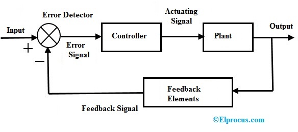
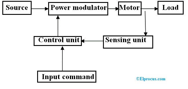
. The block diagram does not represent the physical nature of a control system. Any system can be described by a set of differential equations or it can be represented by the schematic diagram that contains all the components and their connections. The open-loop control system block diagram is shown below.
The function of the CPU is to store and run the PLC software programs. Identify all the components inputs and. Any system can be described by a set of differential equations or it can be represented by the schematic diagram that contains all the components and their.
Components of Linear Time Invariant Systems LTIS Figure 3. It helps to perform the. Use Createlys easy online diagram editor to edit this diagram collaborate with others and export results to multiple image formats.
The arrow head pointing towards the block indicates the input. Two different physical system may have same block diagram. This block diagram is shown in the following figure.
You can edit this template and create your own. Block Diagram Reduction Figure 1. The total output is CCC 1 G2G2 A A IGIR 78 REDUCTION OF COMPLICATED BLOCK DIAGRAMS The block diagram of a practical feedback control system is often quite.
Block diagram components Figure 4. The output of the summing point is. Functional Software Electrical etc.
The closed-loop control technology allows our system to constantly calculate when to apply the eddy current brake while continuously measuring the effect of the brakes application and. Block diagram control system calculator. It is difficult to determine the actual composition of individual elements in a system.
Also a physical system may not. Ad Templates Tools To Make Block Diagrams. The disadvantages of block diagram representation are.
Begin by opening a Creately workspace you can make edits to multiple pre-made templates or start creating your block diagram from scratch. Output of the block G s is G s R s. In the following diagram the input can be given to the control system so that the required output can be obtained.
Fig 21 shows an element of the block diagram. Central Processing Unit is the heart of the PLC system. Block Diagram in control systems.
Single block diagram representation.
What Is A Computer Block Diagram Quora
Closed Loop Control System Block Diagram Types Its Applications
What Is A Computer Block Diagram Quora
Sensors Free Full Text Nonorthogonal Aerial Optoelectronic Platform Based On Triaxial And Control Method Designed For Image Sensors Html
Precise Digital Temperature Controller Circuit Working And Its Applications
Damping Ratio In Control System Working Its Cases
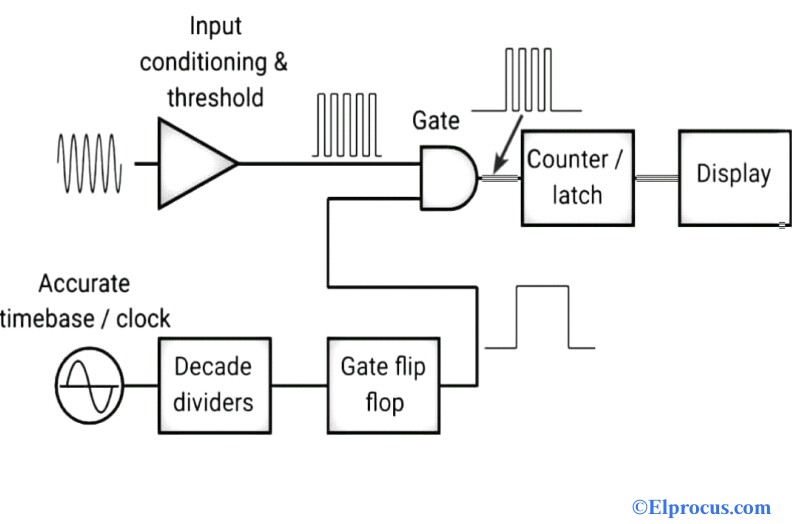
Frequency Counter Block Diagram Circuit Types And Its Applications
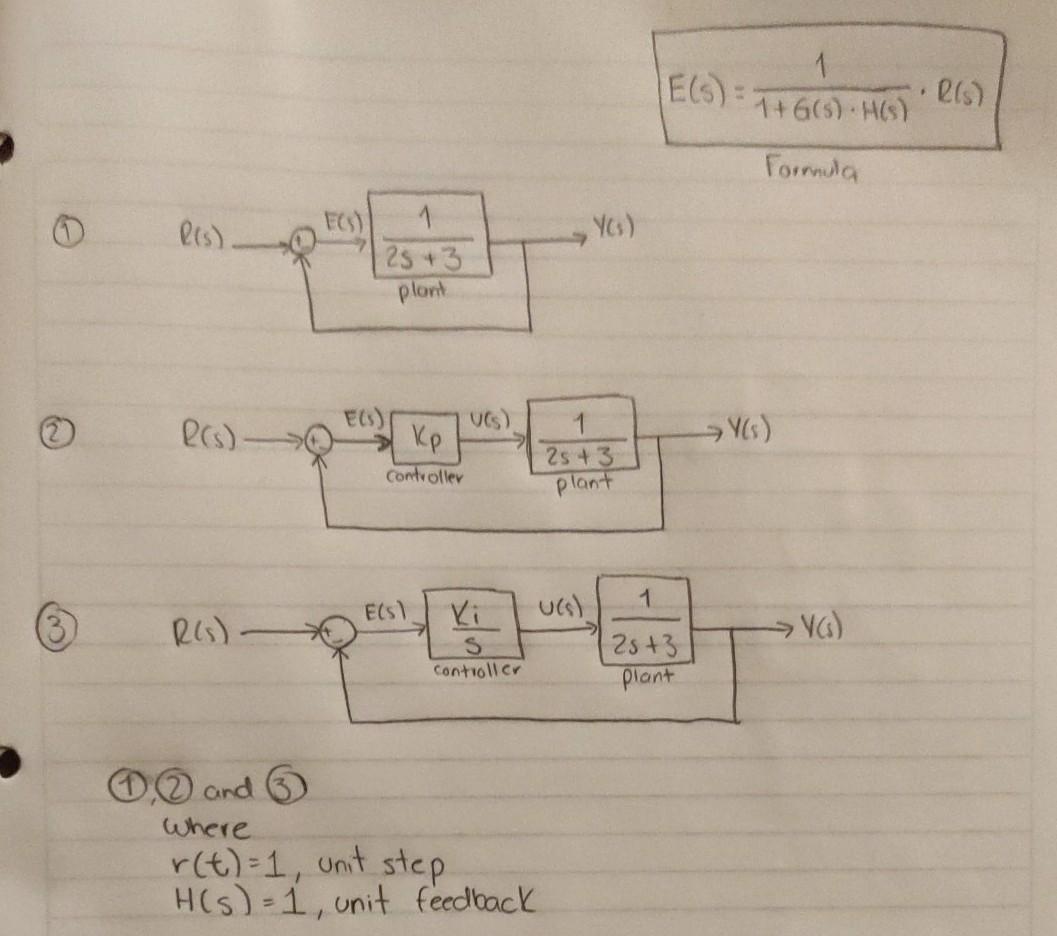
Solved Calculate The Steady State Error Ess In The Following Chegg Com
2
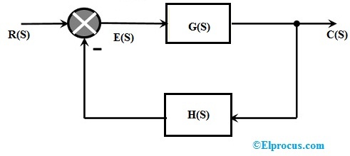
Closed Loop Control System Block Diagram Types Its Applications
Solved Consider The System Represented By The Block Diagram Of The Following Figure The Closed Loop Transfer Function T S Y S R S Is Select Course Hero
Solved Consider The System Represented By The Block Diagram Of The Following Figure The Closed Loop Transfer Function T S Y S R S Is Select Course Hero

Three Element Drum Level Control System Control System Process Control System
Electric Drive Types Block Diagram Classification And Its Applications
What Is A Computer Block Diagram Quora

System Block Diagram The Difference Between G Z H Z And Gh Z G Z H Z Z G S Z H S Gh Z Z G S H S Usually G Z H Z Lie Algebra Block Diagram Diagram
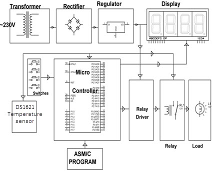
Precise Digital Temperature Controller Circuit Working And Its Applications